200L steel barrel injection port screw ring locking process and mold improvement
Luo Quankui
Abstract: This paper analyzes and compares the new and old technology of the screw ring of the 200L steel drum injection port, and puts forward the improvement scheme and the conclusion that it has application value after implementation.
Keywords: spiral ring locking process mould
Since its invention of steel drum sealer, FCAGE has been used for more than half a century. Due to its simple structure and convenient installation and use, the world has been used all over the world. The 200L steel drum of the factory uses the steel barrel sealer of this structure. The closing device of the structure adopts the form of lock, and the quality of the lock directly affects the sealing performance of the sealer. In order to improve the sealing quality of the 200L steel drum injection port of our factory, it is decided to research and improve the 200L steel barrel injection port locking process mold.
First, the original lock loading process, mold structure and working principle
Before introducing the lock-in process, we will introduce a process before the lock-up: the bottom cover punching process.
1. Bottom cover punching process, die structure and working principle
The bottom cover punching process includes punching, flanging, and pressing octagonal pockets. The three processes are completed at one time, using a composite mold. The mold structure is shown in Figure 1, and the bottom cover is positioned with a positioning pin. Down the slider, the punching punch 2 first contacts the convex and concave die 4, and the bottom cover is punched out of a small hole; the slider continues downward, and the workpiece descends along with the die 3 and the unloading plate 5, through the die 3 and The action of the male and female molds 4 turns the small holes into straight wall holes; finally, the outer octagonal shape of the male and female molds 4 and the inner octagonal shape of the female mold 3 press the bottom cover out of the octagonal recess. When the slider is ascending, the unloading plate 5 causes the workpiece to leave the convex and concave die 4, and the workpiece is taken out, and the punching process is completed.
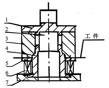
Figure 1 punching and flanging die
1, the upper mold base; 2, punching punch; 3, eight square concave mold; 4, convex and concave mold; 5, the discharge plate; 6, spring; 7, lower mold base
2, the original lock loading process, mold structure and working principle
The original locking process is a winding edge die work to wind the workpiece into a circular arc along the winding edge. The mold structure is shown in Figure 2. After the bottom cover punching process is completed, the coil is placed by hand on the bottom cover punching hole, and the two corners are aligned. Then the hand is grasped from the back of the bottom cover by hand, and the bottom cover is closed. Flip 180° into the mold positioning seat and lock it after leaving the hand.
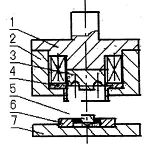
Figure 2 Note inlet original lock mold
1. Upper mold base; 2. Upper fixed ring; 3. Locking die (rolling edge die); 4. Pressing ring; 5. Positioning core; 6. Lower fixing ring;
There are some shortcomings and problems in the above locking process: a. The operator is required to flip the workpiece back and forth, increasing labor intensity and reducing labor efficiency; b. The operator is required to manually send the coil and the bottom cover into the mold together by hand. On the one hand, it brings inconvenience to the operator, reduces the production efficiency, on the other hand brings unsafe factors to the operator; c. When press-fit, on the one hand, due to the workpiece flipping, there will be eight-way misalignment, and on the other hand, the positioning will be inaccurate. Press-fit deflection occurs, which reduces the quality of the lock and affects the sealing of the steel drum.
Due to the shortcomings of the original lock-up process, the above-mentioned problems have been researched and improved on the injection port locking process and mold of the factory.
Second, the development of new packaging technology and new mold
1. Development of new lock technology
The locking of the barrel cover coil is locked by the curling edge mold to straighten the edge of the spiral ring. The winding edge process is a stamping method for rolling the edge of the flange piece (or the stretching piece) into a certain shape, as shown in the figure. 3 is shown. In view of the shortcomings of the original lock-up process, referring to the relevant information, the original process is changed to the anti-locking method. Under the action of the slider, the straight edge of the spiral ring is moved down along the winding edge to form a circular arc shape, and the circular arc shape is wrapped. The flange of the lid is straightened to complete the lock of the lid and the coil.

Figure 3
2. Development of new mold for locking
It can be seen from the above process improvement that the curling die of the original mold must be changed from the upper die to the lower die. Since the original mold winding edge is completed in the upper mold and positioned lower than the lower mold, the positioning is inaccurate. In order to solve this problem, the winding edge mold and the positioning mold are unified. In this way, during the winding process, the workpiece is automatically positioned and positioned by the positioning die to complete the screw locking.
Third, the design of the lock mold
1. Determination of the size of the punching process
Before designing the lock mold, first determine the process size of the punch, and calculate the punch size of the bottom cover by calculation (see Figure 4).

Figure 4 Process size of punching
(a) shape after punching and flanging; (b) front mounting coil; (c) after locking
D1=62.3±0.2mm
d=60.4±0.3mm
H=18.8±0.3mm
h=8.3±0.3mm
b=3.0±0.3mm
Since h2≥b+δ (δ=1.25mm)
Determine h2=4.5±0.3mm
According to the lock process diagram:
H1=Hb-δ-2π
Δ——material thickness, δ=1.25mm
R——Round edge groove radius, R=2.0 mm
Calculated by calculation h1 = 10.0 ± 0.3mm (rounded)
In order to ensure a proper interference fit between the coil and the flange of the bottom cover during locking, D?D1 is required when determining D
According to experience, D=62.0±0.2mm
In order to make the ring after the lock can fully fill the triangular seal area (see Figure 4c), the r value after the punching is not too large, according to experience: r = l.Omm
2, the determination of the size of the lock process
Since the locking process requires that the winding edge die must be rolled back when the locking is installed, and the straight edge that is turned up when the punching is turned over is hooked (see Fig. 4c), the diameter 2R of the winding edge groove is required to be:
2R=3δ+△
Δ——material thickness, δ=1.25mm
△——gap, mm
After calculation, it is determined that: 2R=4.Omm, R=2.Omm
After the lock is installed, the length of the arc of the coil is calculated:
l=2π(R-δ/2)/2
R——Round edge groove radius, R=2.0 mm
Δ——material thickness, δ=1.25mm
Calculated: 1 = 4.3175mm
Therefore l?h (h=8.3mm)
Therefore, the process is feasible.
3, the calculation of lock loading force
Since the deformation of the coil lock (ie, the curling edge) is similar to the flange of the hole, the locking force of the coil can be approximated according to the calculation method of the flange of the hole:
P lock = 1.1πδσs (Dd)
Δ——material thickness, δ=1.25mm
Σs——the yield strength of the material is 196MPa
D——the outer diameter of the coil behind the ring, D=69mm
D——the front aperture d=60.4mm
Calculated: P lock = 8039N
Calculation of discharge force:
P unloading = K unloading × P unloading
Check the table know: K unloading = 0.045
Calculated: P unload = 362N
Therefore: P total = P lock + P unload = 8401N
4, the selection of equipment
Because the total pressure is small, according to the size of the workpiece and the condition of the plant, it is decided to use the original equipment - 63T punch.
5, the structure and working principle of the mold
Based on the original lock mold, a new lock mold was designed. The mold structure is shown in Figure 5. During the locking process, the coil is placed directly into the punching hole of the bottom cover, and the square is aligned. The hand-held bottom cover places the coil on the locking core 3 for centering and sliding. When the block moves down, the press-fit ring 2 first contacts the workpiece, and the angle is corrected and positioned. The workpiece continues to move down under the action of the press-fit ring 2, and the upper part of the circumference of the coil (unthreaded part) is under the action of the lock core 3 Rolled into a circular arc shape, hooking the straight edge of the bottom cover up, and the slider reaches the bottom dead center. The slider returns, and the returning plate 6 withdraws the workpiece under the action of the spring 7, completing the locking of the coil.

Figure 5 Note inlet new lock mold
1, the upper mold base; 2, press-fit ring; 3, lock core; 4, workpiece; 5, fixed ring; 6, return plate; 7, spring; 8, lower mold base
Fourth, the material selection, assembly and trial production of the mold
The mold was made of 45# steel, and the trial production was carried out after assembly, and satisfactory results were obtained. No leakage occurred in the air tightness test; in the sampling hydraulic test, the withstand voltage reached the packaging requirements of the international maritime dangerous class I dangerous goods; no leakage occurred in the drop test of 1.8 m height.
V. Conclusion
Through the improvement of the injection ring screw locking process and the mold, the following conclusions can be drawn:
a, the sealing is improved;
b, the pressure resistance is improved;
c, security has improved;
d, reduce labor intensity and improve production efficiency;
e. Low implementation costs and application value.
Such a process is also suitable for the locking of the vent coil, which needs to be further promoted.
Nail Polish Bottle,Makeup Containers,Makeup Jars,Glass Makeup Containers
Shijiazhuang HuangJia Trading Co., Ltd , http://www.hj-cosmetic.com